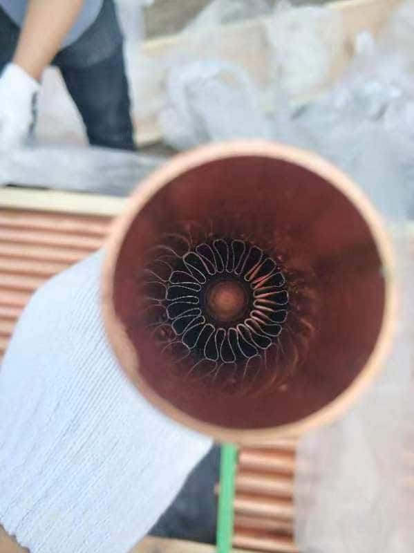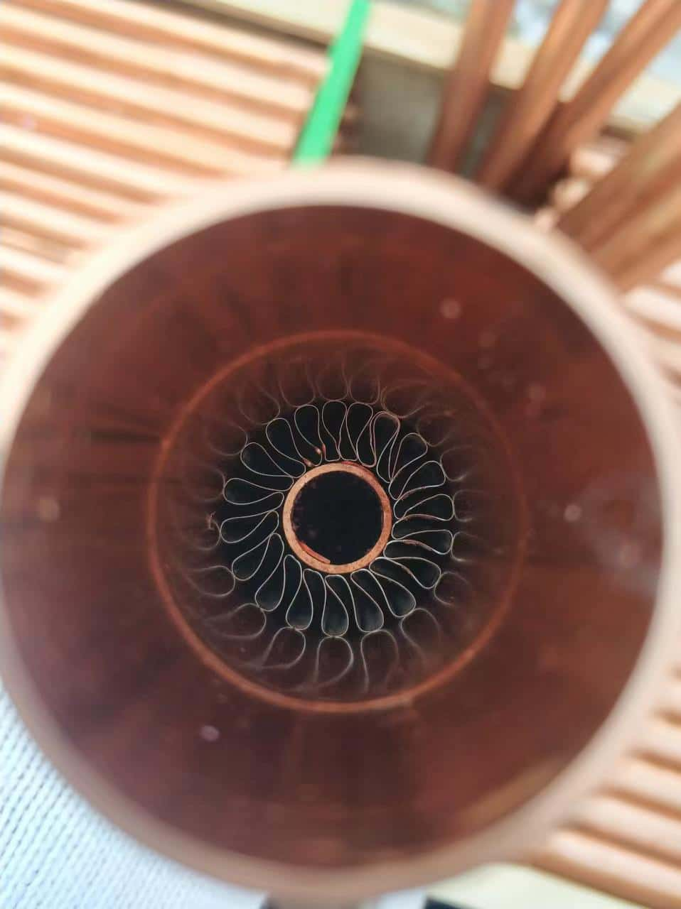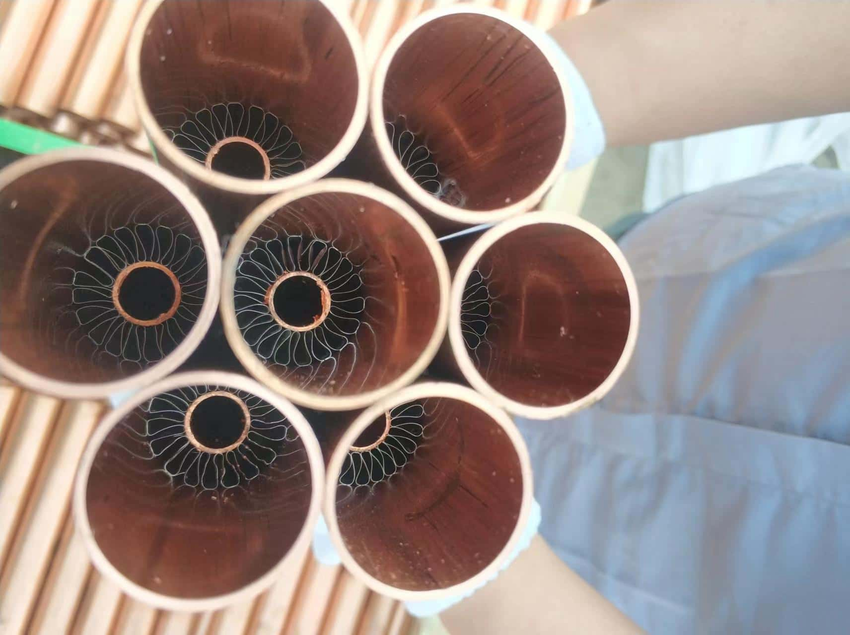
Internally Finned Tube Dimensions
| U.S. | Metric | ||||||
|---|---|---|---|---|---|---|---|
| Tube (OD) | Max Nozzle | Fin Height | Twist Rates (per rev.) |
Tube (OD) | Max Nozzle | Fin Height | Twist Rates (per rev.) |
| 2-3⁄8” (12 Fins) |
1-7⁄16“ | 1⁄4 inch | 12 inches | 60 mm | 37 mm | 6.4 mm | 305 mm |
| 2-3⁄4” (18 Fins) |
1-9⁄16“ | 3⁄8 inch | 18 inches | 70 mm | 40 mm | 9.5 mm | 457 mm |
| 3-1⁄4” (15 Fins) |
2-3⁄8“ | 1⁄4 inch | 12 inches | 83 mm | 60 mm | 6.4 mm | 305 mm |
| 4-1⁄2” (18 Fins) |
3-5⁄16“ | 5⁄16 inch | 20 inches | 114 mm | 84 mm | 7.9 mm | 508 mm |
| Special fin heights and twist rates available upon request. | |||||||

Inner finned tubes advantages
1. The heat exchange efficiency is greatly improved, and the effect of energy saving and water saving is remarkable
2. It can withstand high temperature and high pressure with low resistance drop
3. The heat exchanger has small volume and small floor area
4. Low investment and short return period
5. Reduce the maintenance cost of users

The main working conditions are as follows:
(1) cooling and heating of various process gases;
(2) condensation of various process gases;
(3) recovery, cooling, and condensation of tail gas of various process gases;
(4) high (low) viscosity of liquid and water heat exchange;
